Structural Biology Core
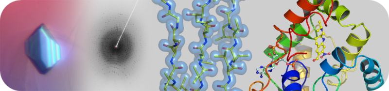
The Structural Biology Core Laboratory has state-of-the-art instrumentation and expert staff to enable detailed structural and biophysical studies of biological macromolecules in human health and disease. Our capabilities include X-ray crystallography, NMR spectroscopy and a new Cryo-EM facility for single particle analysis and structure determination in addition to resources and infrastructure to assist users with protein production and characterization.
Contact
Shaun K. Olsen, Ph.D.
Director
210-450-3091
Email: OlsenS@uthscsa.edu
Alex B. Taylor, Ph.D.
Associate Director
210-567-3781
Email: TaylorAB@uthscsa.edu
Kristin E. Cano, Ph.D.
Technical Director
210-567-8706
Email: CanoK@uthscsa.edu
Lijia Jia, Ph.D.
Cryo-EM Facility Manager
210-450-8681
Email: JiaL@uthscsa.edu